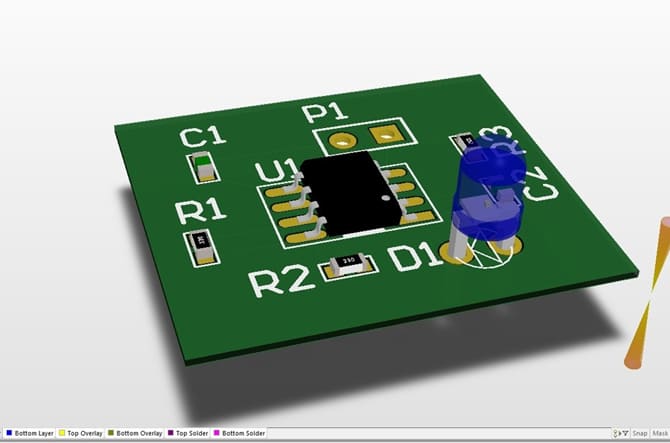

The ones with holes are for ‘through hole’ type components and the ones without are for surface mount components. The photo below is a prototype PCB of our cell balancing system before the components being soldered on. A footprint defines the land layout pattern of a component on a PCB (the shiny silver pads in the photo below). When designing PCBs for various purposes, it’s almost impossible to avoid the headache of finding footprints because the manufacturer in most cases only supplies us with a data sheet but no footprint files. For example, the safety system, voltage monitoring system, cell balancing systems are designed and manufactured onto PCB boards. At MUR, we design and manufacture PCBs for low voltage systems, battery management systems, electric power train, accumulator etc. Custom designed PCBs can achieve the exact function we want while saving all the spaces we can and plus the circuit is more stable on a PCB due to its protective coating. Printed circuit boards (PCB) are essential in almost all commercial devices that contain some form of electrical circuits because of its flexibility and compactness. MUR Blog - How to Manually Create Footprints in Altium Designer


 0 kommentar(er)
